|
Damond Li Project
|


|
|
Damond Li Project
|
|
Video Demonstration of Controls and Operation of Ball-Balancing Platform:
Video Demonstration of Initial Testing:
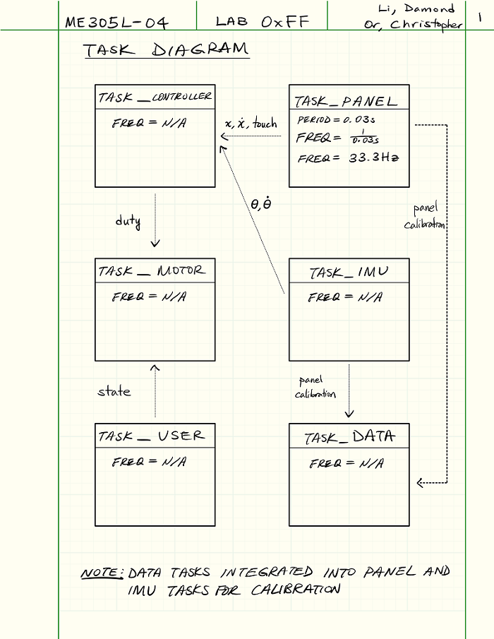
The first step taken for this term project was to create a task diagram describing how
our program operates. Please refer to Figure 1 for the task diagram. From the task
diagram, there were 5 main variables that will be shared across the different tasks:
linear position (X and Y), linear velocity (X and Y), angular position (pitch and roll),
angular velocity (pitch and roll), and duty cycle. The resistive touch panel is
responsible for the linear positions and velocities. The IMU is responsible for the
angular positions and velocities. The controller is responsible for determining the duty
cycle. With that in mind, it would then be a matter of getting each task to output their
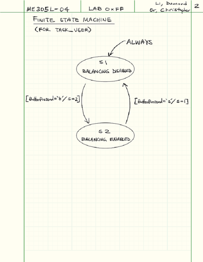
respective data. The finite state machine implemented for our user task is shown in Figure 2.
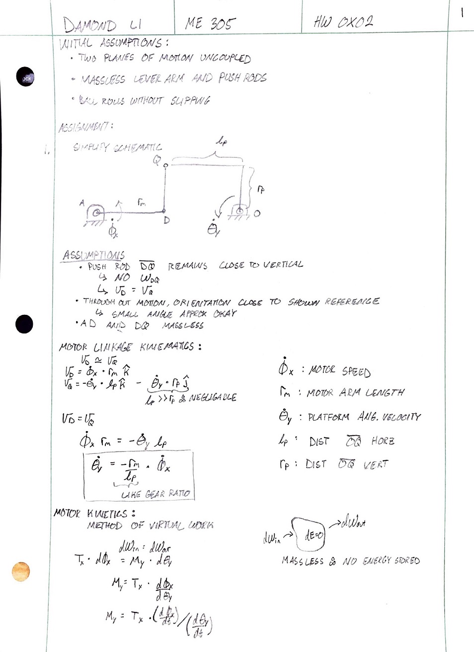
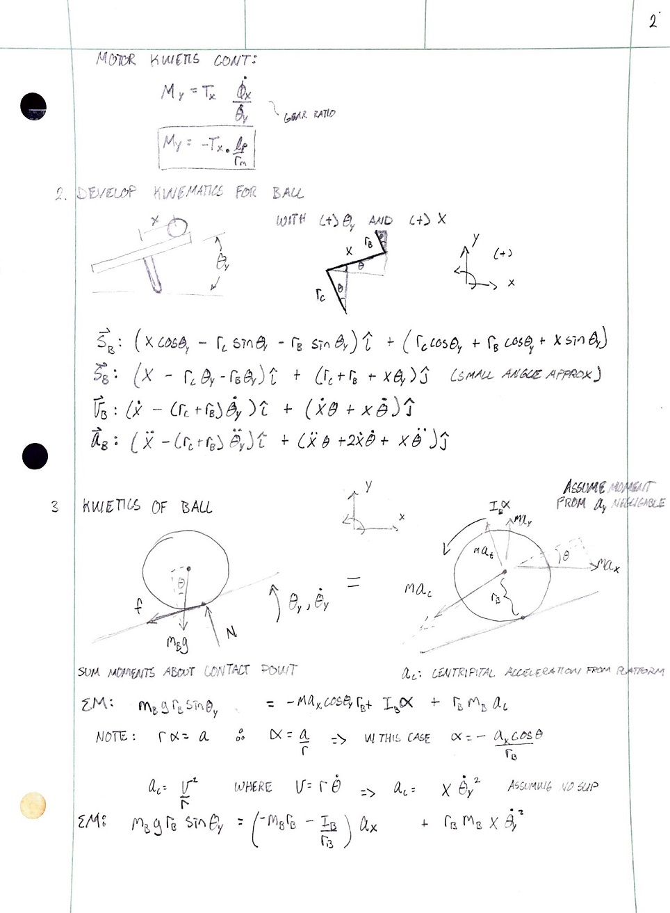
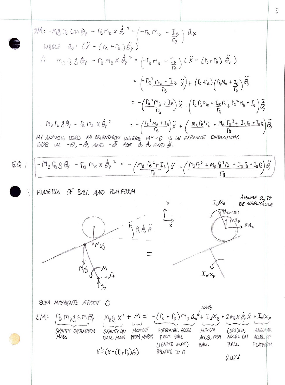
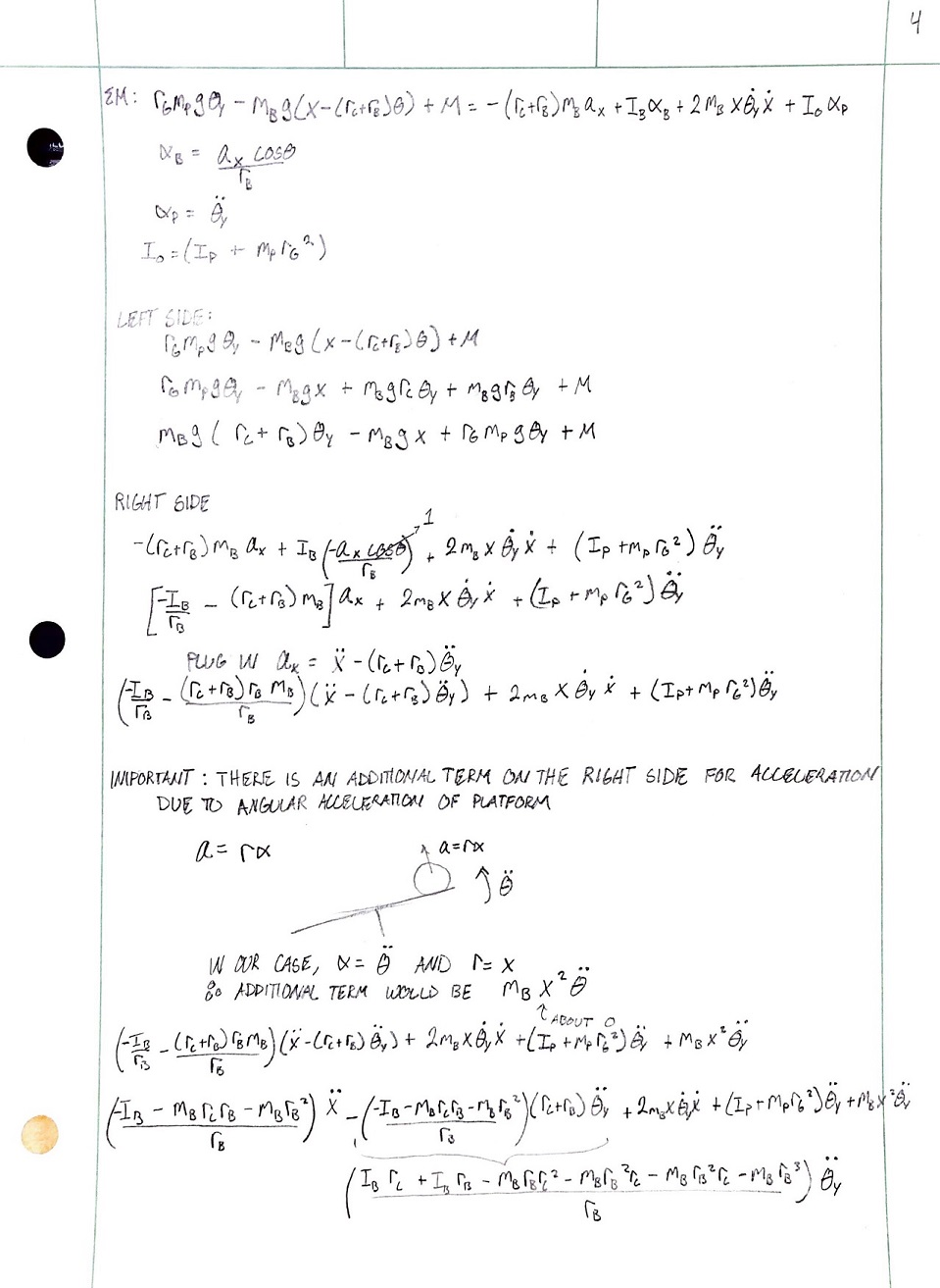
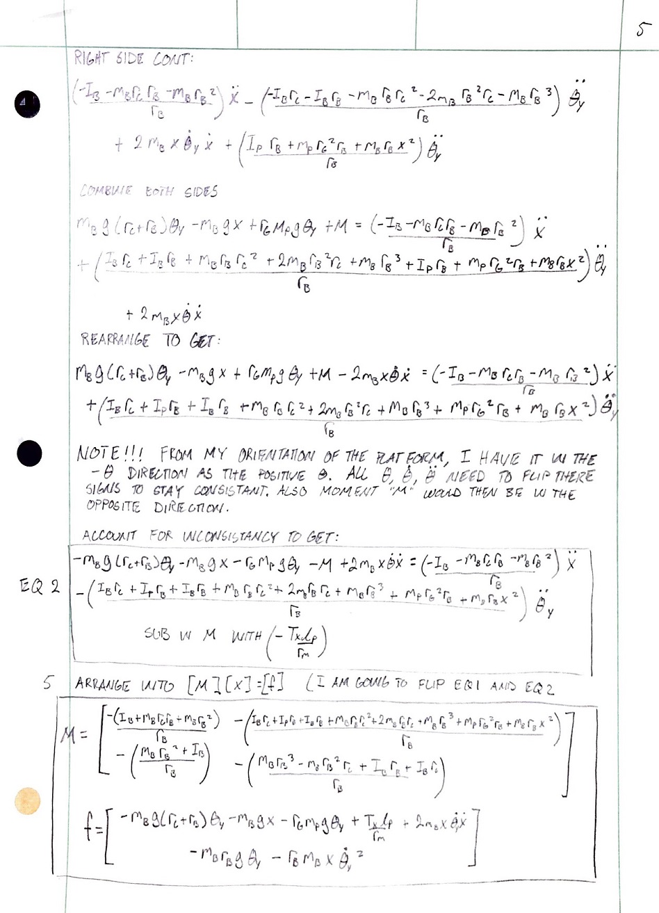
To model our system, we analyzed the kinematics and kinetics of two systems. The ball
rolling without slip, and the ball and platform as a whole. We then found the equations
of motion of the system that are used in the Simulation section. The hand calculations
used for modeling are shown below:
Below is the MATLAB livescript used to complete the Ball and Platform simulation for HW0x03.
Please click on the following to see the full MATLAB Simulation:
To determine the gains to run our full state feedback controller, a MATLAB script based
off of HW0x03. It was determined that it would be extremely difficult to balance one of
the smaller ball bearings due to its small mass. When the smaller ball bearings roll
across the touch panel as the platform is moving, there are instances where the ball
lifts off from the platform which can be problematic for the controller. A larger ball
bearing with a larger mass is necessary in order to maintain constant contact with the
touch panel. Accordingly, the MATLAB script from HW0x03 was updated with the larger ball
mass and radius to determine the open-loop Jacobian matrix. A closed-loop matrix was
derived by manipulating the open-loop matrices. The poles of the closed-loop matrix was
chosen so that the closed-loop response will have a natural frequency of 8.2, a damping
ratio of 0.8, and two poles at -16 and -17. The gain values were then calculated with the
desired response. Please click HERE for the MATLAB
script used for this calculation.
For the term project, many of the tasks from Lab 0x01, 0x02, 0x03, and 0x04 were updated
to only contain the necessary methods to run our ball and platform system. For example,
task_motor.py previously contained methods to run the motors at a specified speed and
gain value for 10 seconds. That method has been removed from task_motor.py for the term
project. In addition, the hardware for the motor has changed in that the motor is able to
output three times the torque and the motor can no longer fault.
In the middle of debugging the program, it was observed that the program had no problem
balancing the ball in one of the two directions. It was later observed that the source
of the problem is due to the specified coordinate system. In one direction, a positive
rotation causes the ball to accelerate in the positive direction. However, in the
perpendicular direction, a positive rotation causes the ball to accelerate in the
negative direction. The full state feedback controller is designed for the former. In
order to resolve this issue, the positional data was simply multiplied by a negative
before entering the full state feedback controller.